3d Object
|
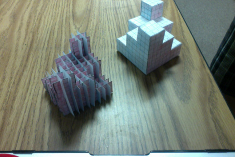
In this project, we created 3d models using small blocks arranged in a 3x3 configuration. The criteria; make an interesting shape be removing blocks, and then creating an isometric drawing of this shape. Based off of this drawing, an orthographic drawing was created, then geometric net, which was folded up into the original shape. A slice form sculpture of our 3D object was created by utilizing all three of these illustrations.
|

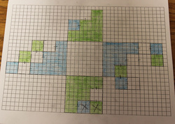
Orthographic Drawing
|
Geometric Net
|
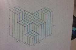
Isometric Drawing
|
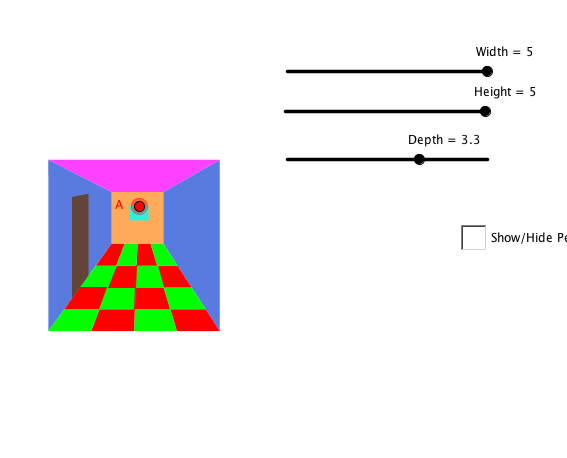
Perspective
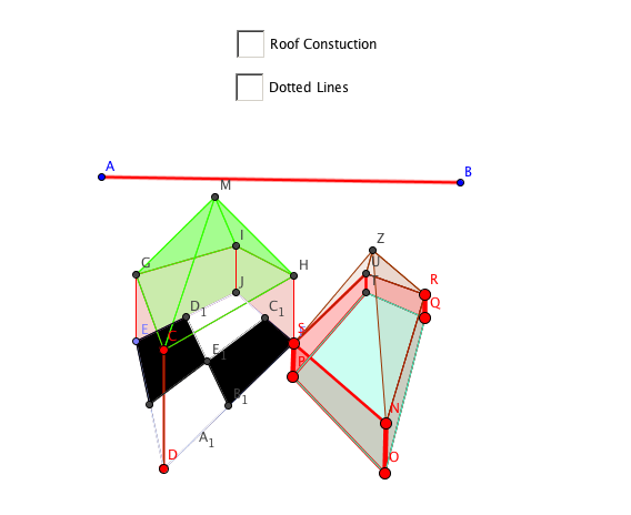
Geogebra Labs were used to create 3D rooms from a one point perspective and a two point perspective.
|
|
My Anamorphic 3-D Drawing Project
|
|
|
|
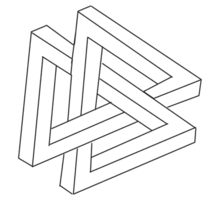
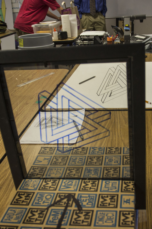
Anamorphic in short is a projection that appears proportional from one point of perspective. This means that a shape or object projected onto a surface will look “normal” to the human eye from a certain perspective. When this perspective changes the object cannot be seen as normal. The projection is not proportional from different perspectives.
The supplies that I used to create this drawing were a transparent vertical plane with a 3D image printed on it. This image had to remain perpendicular the the ground. A printed image of a 3D object (Impossible Shapes, Optical Illusions, 3D Shapes) was traced onto the pane of glass or transparent plastic and held up vertical by something. A shoebox was usually used to stabilize the clear pane. This image was then projected onto a poster board and then shaded.
The anamorphic drawing is the result of a projection because the perspective of the glass pane is projected onto the sheet of paper. This projection was achieved by looking throughout the glass pane and making dots onto the paper to maintain proper perspective to be able to see the image of normal. This was made by telling a partner to make points on the paper how we saw it through the picture frame.
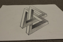
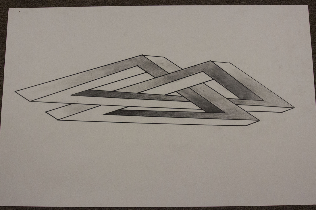
A part of this project that was difficult for me and my group was trying to get the points accurate. We had to stand in the exact spot for the whole period trying to get the points correctly, but from the perspective that we were at, the points that were drawn could not be seen, so lining up the shape after it was moved for the next period was difficult.
The supplies that I used to create this drawing were a transparent vertical plane with a 3D image printed on it. This image had to remain perpendicular the the ground. A printed image of a 3D object (Impossible Shapes, Optical Illusions, 3D Shapes) was traced onto the pane of glass or transparent plastic and held up vertical by something. A shoebox was usually used to stabilize the clear pane. This image was then projected onto a poster board and then shaded.
The anamorphic drawing is the result of a projection because the perspective of the glass pane is projected onto the sheet of paper. This projection was achieved by looking throughout the glass pane and making dots onto the paper to maintain proper perspective to be able to see the image of normal. This was made by telling a partner to make points on the paper how we saw it through the picture frame.
A part of this project that was difficult for me and my group was trying to get the points accurate. We had to stand in the exact spot for the whole period trying to get the points correctly, but from the perspective that we were at, the points that were drawn could not be seen, so lining up the shape after it was moved for the next period was difficult.
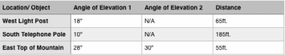
Trigonometry
East Top of Mountain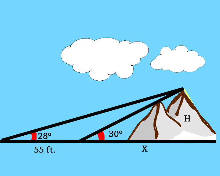
Tan30=(H/X)
Tan28=(H/55+X) H=X*Tan30 H=(X+57)Tan28 (H=XTan28)+(57Tan28) XTan30=(Xtan28+57Tan28) XTan30-Xtan28=57Tan28 X(Tan30-Tan28)=57Tan28 X=57Tan28/Tan30-Tan28) X=664.042ft H=383.385ft |
West Light Post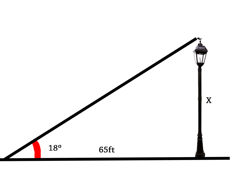
Tan18=(X/65)
X=21.12ft |
South Telephone pole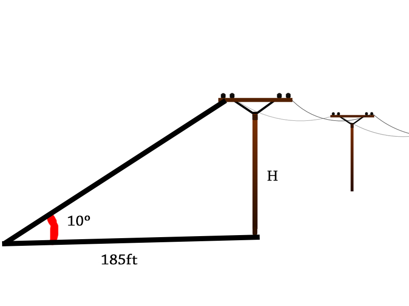
Tan10=(X/180)
X=32.62ft |
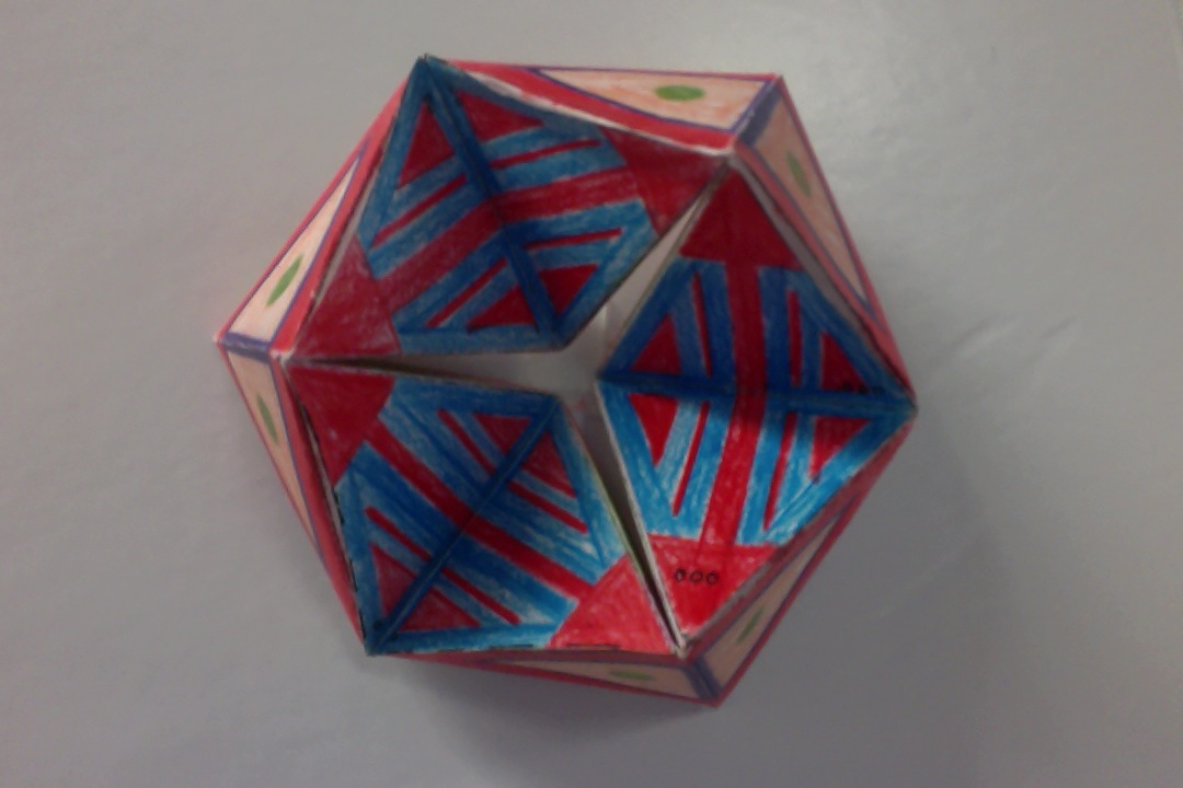
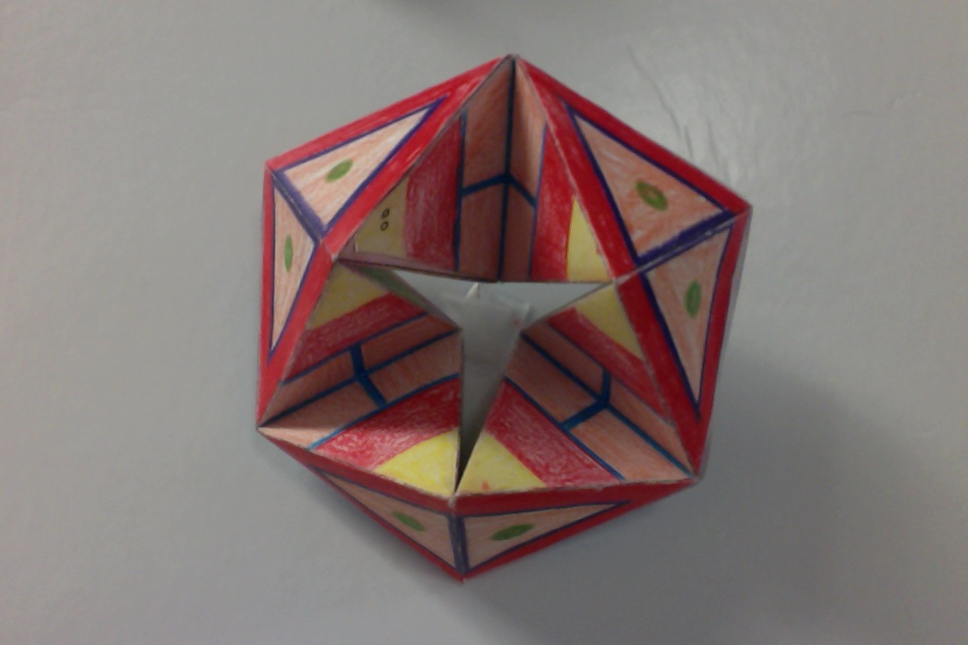
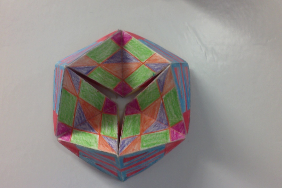
Hexaflexagon
|
|
|
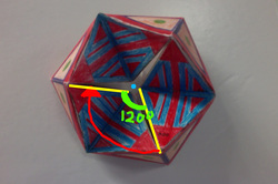
My Hexaflexagon utilizes rotational symmetry in the design. All three sides that make up the hexagon are very close to symmetrical. One side is rotated 120 degrees, and then rotated 120 degrees more to make up all three sides. For example, If The yellow line on the bottom of the hexaflexagon is rotated onto the other yellow line, it is a 120 degree rotation around the blue point. The blue point is the center of rotation.
A feature of my own hexaflexagon that pleases me is the symmetry on all the sides. I also like the color themes that I chose. The colors and symmetry are very pleasing to the eye. A refinement I would make is to come up with more elaborate designs and design the colors and shapes to be more interesting. I would do this because I now know how the sides line up. I learned that I definitely have more patience for coloring than I thought. It usually is hard to be patient with detail things such as coloring on small triangles, but I enjoyed this small project.
Snail Trail Graffiti GGB LAb
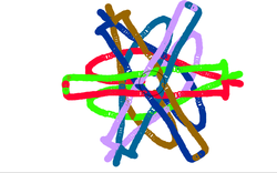
There were lot of geometry concepts used to create this design. There is rotational symmetry, angles and line-reflection symmetry. I also gained a lot of experience by using Geogebra to create this project. Geogebra is a program that we use in geometry to "play" with different shapes by reflecting and rotation. To make this project, I created 6 lines of that were equally placed and then created one pre image to be reflected over each of the lines. I changed the color of each image reflection. Then upon dragging the pre image with the tracking trails on it makes cool designs. After this project, I understand more how to utilize reflection and rotations in geometry. It was interesting to see how the images would act when I dragged the pre-image around.
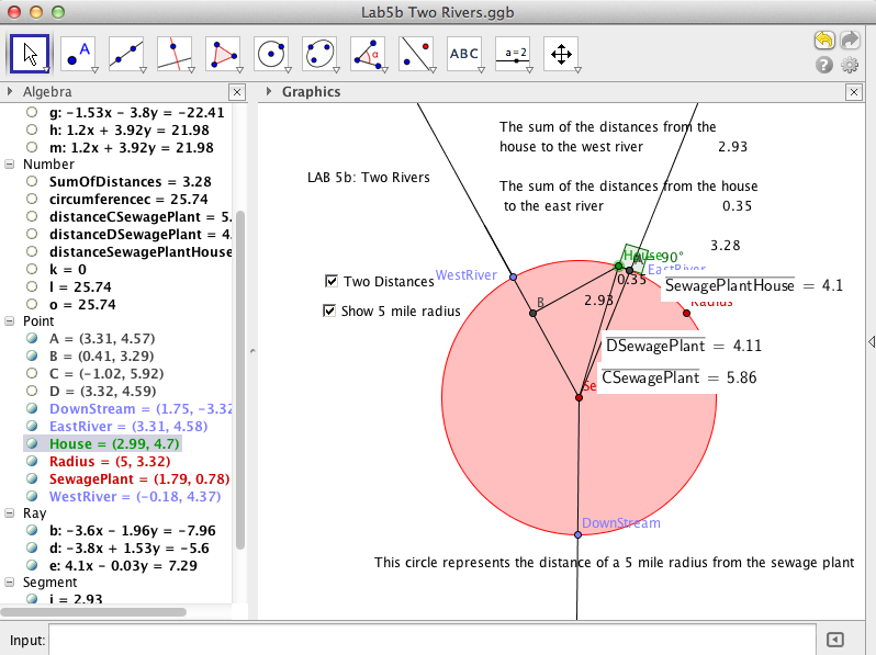
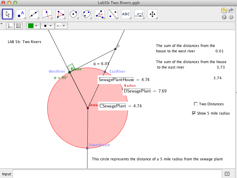
Two Rivers GGB Lab
In this project, We were supposed to find the shortest distance for the sum of two lines to two points. We did this by simulating a river and house. This was done on Geogebra. The problem was:
There is a sewage treatment plant at the
point where two rivers meet. You want to build a house near the two rivers (upstream from the
sewage plant, naturally), but you want the house to be at least 5 miles from the sewage plant. You
visit each of the rivers to go fishing about the same number of times but being lazy, you want to
minimize the amount of walking you do. You want the sum of the distances from your house to the
two rivers to be minimal, that is, the smallest distance.
|
|
In the 1st picture, the location of the house is not acceptable. The problem was to find the shortest difference to watch of the rivers from the house, but this was not the case. In geometry, I learned the the perpendicular bisector is the shortest route as shown in the 2nd picture. The perpendicular bisector shows the shortest route to both rivers. The house could either be built on the east or west river.
|
The geometry concepts that lead me to the conclusions are concepts that I had learned before. The perpendicular bisector is the shortest route. I thought that this was interesting because the line straight across in the middle of the two rivers looks shorter. I leaned about tangent lines and bettered my skills with Geogebra.
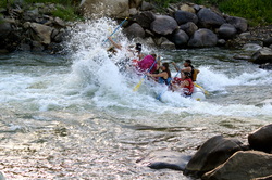
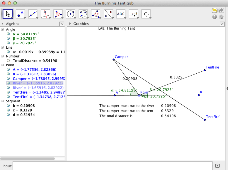
The Burning Tent Lab
This GGB lab was made to find the shortest route from a location where you are to a river and then to a tent that has caught on fire. The sum of two lines was supposed to be the shortest.
|
The first picture shows that the location of where you want to go to the river and get water to bring to the tent as an inefficient way. It is a very long way to run. The 2nd picture shows the most efficient way to get water to put out the fire on your tent. I leaned that If the Tent is reflected over the river, the shortest path is that one line that goes across the river, but the tent is on the same side of the river that you are. If the straight line directly to the tent is bent at the intersection of the river back up towards the tent, it is the the same distance to the reflected tent.
|
I learned that reflection shows the least distance in this particular project. I never thought of it this way. Some geometry concepts that were utilized in this project were reflection, and measuring angles. The reflection of the tent helped me see what I am really doing, because it made sense to me shown this way. Reflecting lines was what this project was about.
